There is a debate around the best way of addressing the first mmWave use case for 5G, Fixed Wireless Access (FWA) REF [1 and 2]. The debate is focusing on how to best create the best link budget for an active electrically beam steered RF system, where companies argue how to reach the right performance. The active component in the system is the RFIC, which is the part that the debate is mostly centered around, since that is where the power amplifiers (PAs) are located. The antenna is a completely passive component and the main interest around the antenna is centered around how low losses you can achieve, and at which cost. The antenna generates the gain via the available effective area, which is directly proportional to the gain. We believe that there are different solutions for different part of the 5G mmWave system, which depends on what use case you are trying to address and which part of the infrastructure equipment you are developing. How is the mmWave radio signal amplified in the PA and how is the best gain and lowest loss antenna designed? These questions as well as size and power consumption are important factors to consider when developing mmWave 5G systems. In addition to the technical aspects, we must also understand how the market will develop over the coming 10 years.
Looking at the SNS research report “5G for FWA (Fixed Wireless Access): 2017 – 2030”, the total number of units that have one antenna or multiple RF transceivers, will in 2021 be 5.9 million and in 2028 60 million. Of which in 2021, the total of 15% are “base stations”. The traditional macro bas station (BTS) will only cover 0.8% of the total market, while remote radio heads (RRH) cover 10% and small cells 3.6%. The main bulk will be CPEs with a market share of 85% (Customer Premises Equipment). A similar distribution is estimated for 2028.
This means that approximately 85% of the total number of RF modules that will be sold for the 5G mmWave market will be located in indoor or outdoor CPEs.
A 5G system includes multiple sub-systems which should be optimized and operate together. Sivers IMA develops and delivers the RF sub-system (mmWave only). The RF subsystem transfers the radio signal all the way from the baseband signal (from the modem) into the air. How the RF solution is architected is very dependent on the use case and what you like to achieve, e.g. if you want to reach 150 meters or 1000 meters. There are four parts that sums up the total effective isotropic radiated power (EIRP) in an RF system (i.e the total “power” or “signal strength”):
- The RF power amplifier itself, i.e. its output power and linearity performance
- The number of power amplifiers tiled together in the antenna array
- The gain achieved from the antenna. For a given frequency, the antenna’s effective area is proportional to the power gain, i.e. the size of the antenna is the main driver of the total gain that the antenna can achieve Ref [10]
- Losses in the substrate, wave guides and packages
When the system is designed, you need to follow the rules and regulations in each country from their regulatory bodies, for example the Federal Communications Commission (FCC), an independent agency of the United States government, providing regulations for interstate communications. FCC was early out with 5G mmWave regulations for 28/39 GHz (i.e. mmWave for 5G). Below you can read the comments that were provided to FCC by some of the large companies within the eco-system around power limits for macro base stations.
From FCC [ref 1] “Most commenters believe that we should adopt a higher power limit than the 62 dBm EIRP proposed in the NPRM, but initially disagreed on the specific limit we should adopt. Qualcomm, Samsung, Straight Path, and Verizon state that power limits in the 68-75 dBm range are appropriate, while Ericsson, Nokia, TIA, XO argue that power limits in the 82-85 dBm range are necessary. More recently, Verizon, Samsung, Qualcomm, Intel, Nokia, and Ericsson (the “Consensus Filers”) have reached a consensus that 75 dBm EIRP is a reasonable transmission power limit”.
To put the power levels into perspective, the power in dBm can be translated into Watts:
• 75 dBm is equal to 30.000 Watts of transmitted power!
• 65 dBm it equal to 3.000 Watts
• 43 dBm is equal to 20 Watts
As you can see, the 75 dBm EIRP transmission power limit is quite some power, hence that will be quite a different use case than the lower power levels, which require completely different solutions. We believe that the 65-75 dBm use case will mostly be used for macro base stations (only 0,8% of the market). Looking at the unlicensed spectrum FWA access use case, were FCC allows the use of 57-71 GHz and WiGig (802.11ad) is the main standard. Following the FCC 60 GHz rules, the total link budget for multi-Gbps (>2 Gbps) link is in the range of 125-130 dB, which can give a total distance of up to 400-500 meters (at 69 GHz, Rain zone E, 99,99% availability, 1-2 GHz bandwidth), using an outdoor CPE. For 5G mmWave, it has been argued that the total link budget needed is around 150-165 dB and for up to 500 meters using a self-install indoor CPE, due to losses in walls and windows i.e. none line of sight. For mmWave FWA you need to think of the challenge with line of sight solution or near line of sight, which of course would be the preferred case for mmWave. Some parties argue, that it is not very common that you will have more than 300 meters from the base station to the user equipment without getting trees (i.e. foliage issues with leaf’s, buildings, etc) between the base station and the user equipment. More about how to address this below.
Samsung just released their line-up for 5G mmWave, being the first company that has approval by FCC for both indoor and outdoor CPE (see reference 6 and 7). Please note that indoor CPEs (or transportable station as it is called by FCC) will need high power due to losses in windows and walls, up to 55 dBm (~300 Watt) is allowed by FCC. Samsung offer an indoor CPE with 55 dBm ref [7] EIRP and an outdoor CPE with a maximum of 40 dBm (10 Watt) ref [6] EIRP. Some companies argue that the extra dBs needed to be able to use a self-install indoor CPE compared to an outdoor CPE that needs to be professionally installed cannot be defended from a power consumption, i.e. environmental point of view. The extra minimum 15 dB that you need to add to the total link budget to get the same distance will necessitate approximately 30x more power consumption (assuming the same antenna gain). Hence a 10-40 Watt outdoor CPE is what we think is the most reasonable solution to meet the total needed system gain and link budget, based on the above reasoning around line of sight and power consumption. A macro cell base station at 65-75 Watt will have very high-power consumption based on the EIRP levels needed to reach 3000-30.000 Watts. As you can see from the SNS research data, this use case is hence not too common for mmWave, only 0.8% of the market in 2021 and 0.6% in 2028. Small cells and RRH will hence be more interesting for 5G mmWave, which we can also see in the corresponding volumes. A realistic output power for small cell and RRH is around 55-60 dBm (300 to 1000 Watts), but there will also be a need for even smaller base stations with output power levels down to 40 Watt (46 dBm). These CPEs and small cells/RRH systems will offer a system gain and link budget that will be good enough for a FWA line of sight use case of around 300 meters.
Hence our assumption for FWA mmWave 5G infrastructure solution is:
1. 55-60 dBm – for small cell or RRH
2. 40 – 46 dBm – for Outdoor Customer Premises Equipment (CPE)
How do you achieve an EIRP around 43 or 60 dBm?
The formula is:
EIRP = 10log(N) + Ge + Powerelement + 10log(M) – Losses
Where N is the number of elements in the array, Ge is the gain for each antenna element, Powerelement is the average power achieved from each PA when transmitting a modulated signal at some specified level, M is the number of PAs and losses are the combined loss in the material, wave guides or strip line etc.
The PAs that offer the highest output power and most efficient PAs available today are GaN amplifiers, which for example ref [1] is arguing for. Another technology that can be used is Silicon Germanium (SiGe), which Sivers IMA and Ref [2] use today.
Table 1 is summarizing how each technology reach 60 dBm EIRP.
| REF 1 (GaN) | REF 2 (SiGE) | Sivers IMA | |
|---|---|---|---|
| Number of elements array | 64 | 256 | 256 |
| Average Output power | +23 dBm | +8,5 dBm | +10 dBm |
| 10log(N) + 10log(M) | 36 | 48 | 48 |
| Ge (antenna element gain) | 5 | 5 | 5 |
| Antenna feed losses etc. | -1.5 dB | -1.5 dB | -1.5 dB |
| EIRP dBm | +62,5 | +60 | +61.5 |
Table 1. Summarizing how each technology reach above 60 dBm EIRP. *Note +3 dB is double output power
Table 2 is summarizing how to reach 43 dBm EIRP with a SiGe solution (please note GaN is not a technology at the moment that address CPE use cases, due to cost).
| Sivers IMA | |
|---|---|
| Number of elements array | 32 |
| Average Output power | +10 dBm |
| 10log(N) + 10log(M) | 30 |
| Ge (antenna element gain) | +5 dB |
| Antenna feed losses etc. | -1.5 dB |
| EIRP dBm | 43 |
Table 2. Summarizing how SiGe technology reach above 43 dBm EIRP. *Note +3 dB is double output power
Hence, for a small cell or a RRH, as you can see in table 1, it is all about the number of elements used and how much power a PA can deliver based on what technology you are using. Are you using GaN, which is a compound semiconductor, or SiGe BiCMOS. Each material has unique properties as well as each technology provider (i.e. Foundry) has their unique solution as well. Then it all comes down to array size, i.e. the number of elements in the array, which shows that a SiGe based array needs to be 4x larger compared to the GaN array. Anokiwave’s 256 array product REF [2], is a 28 GHz 256-Element Active Antenna Innovator’s Kit uses 65 Watt DC power (including all parts, not just the PA etc.) and REF 1 shows a total DC power dissipation of 97 Watts (at approximately 61.5 dBm EIRP) for this GaN solution. This means that the SiGe solution due to the larger array get higher combination gain from the arrays and even if the arrays are bigger the power consumption is less (since the antenna as a passive element do not in itself use any DC power). Array size is of course important and a 4x smaller array might be very interesting depending on the form factor you are looking for. But there is also a cost penalty for GaN, looking at the die size for one PA (i.e. chip area for the PA), according to REF [1] the SiGe die size is 1.2 mm2 and the GaN size is 5.2 mm2, this means that the GaN PA is more than 4x larger the SiGe PA, coincidently this is exactly the size difference of the array size we just talked about. On top of that, the cost for GaN per mm2 is 3-4.5x higher than SiGe according to REF[1]. This means that the PAs in the antenna array are larger and the total cost for them is 3-4.5x more due to the cost and size of the GaN parts, however the antenna can at the same time be 4x smaller. Hence using GaN might not be all that much better, unless you have big constraints on size.
Summary
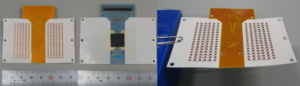
Summarizing all of this, our conclusion is that the 5G mmWave FWA infrastructure will be built mostly on small cells/RRHs connecting to CPEs. The main RF component volume will be on the CPE side which is close to 90% of all units sold. Using outdoor CPEs will probably be the most environmental friendly and the most cost-effective solution and the best fit for mmWave solutions, which is mainly a line of sight technology. For “low” power solutions like CPEs we do not today see a need for GaN technology, due to cost and the lack of integration level that is needed (GaN cannot handle for example digital parts), which can be done in SiGE BiCMOS like Sivers IMA does. Even so, if you like to reduce size of the antenna for a macro cell and are willing to pay a higher price, GaN is the best technology for higher output power base stations (>65 dBm). Sivers IMA’s approach to this, is to offer the right solution for the right use case, we are working with some of the best companies in the world, for example around RF power, with Ampleon REF [4] and working with low loss antenna substrate with Fujikura REF [5]. See for example the cost effective high output power 60 GHz RF module Fujikura has developed based on Sivers IMA RFIC technology, in the below picture which is ideal for CPEs.
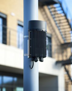
Connecting this RF CPE technology to our customer Cambridge communication Systems (CCS) very innovative 300 degree self-organizing 60 GHz MetNet node (see picture below) and you have an ideal FWA solution, which can deliver wireless Gigabit speed (>2 Gbps) up to a distance of 400-500 meters (at 69 GHz, Rain zone E, 99,99% availability, 1-2 GHz bandwidth), using an outdoor CPE.
Bringing this technology from 60 GHz to 5G mmWave (24-28 GHz) is what we right now are working on. As a great example of what has been done by CCS in a project in the city center of London, which is based on the CCS 24-28 GHz node (please note, this is not using Sivers technology). The project – awarded by City of London Corporation to CTIL, working in partnership with Telefónica O2 – combines the fastest free public WiFi in the UK and 4G small cell network, backhauled by CCS Metnet, please see attached video REF [11] , that shows very well how to use this kind of technology for small cells as well as for future FWA solution. According to REF [9], the size of the 5G system will be important, hence by bringing Sivers IMA highly integrated 60 GHz technology to mmWave 5G, we will be able to offer low cost, lower power consumption and the right size and solution to our customers.
BR
Anders Storm
CEO
Sivers IMA
[1]5G Fixed Wireless Access Array and RF Front-End Trade-Offs, by Bror Peterson and David Schnaufer, Qorvo
[2]All-Silicon Active Antennas for High Performance 5G/SATCOM, David W. Corman, Anokiwave Inc, San Diego, Calif.(please note in this text dBmi is used for EIRP which is the same in this case as dBm)
[4]Ampleon: http://www.ampleon.com/about.html
[5]Fujikura: https://en.wikipedia.org/wiki/Fujikura
[6]Samsung outdoor CPE https://fccid.io/A3LSFG-D1100
[7]Samsung indoor CPE https://fccid.io/A3LSFG-AA100DC/Test-Report/Test-Report-1-3758486
[8]Samsung mmWave 5G release https://news.samsung.com/global/samsung-unveils-the-worlds-first-5g-fwa-commercial-solutions-at-mwc-2018
[9]https://www.fiercewireless.com/tech/samsung-touts-breakthrough-5g-ready-antenna-power-amplifier-at-28-ghz
[10]https://en.wikipedia.org/wiki/Antenna_gain
[11]CCS London network